
 Einloggen


A screw hole in thin aluminum skin over a steel frame looks simple until the bit spins. The paint is slick, a conventional point skates, and the hole is already a sixteenth off before the lips take a real cut. That slip is what a pilot point drill bit is built to stop. A small tip ahead of the main cutting surfaces finds the mark first.
The tip only locates the hole. On the way in, the short nose holds the bit the way a thumbtack holds a paper corner. On the way out of thin sheet or layered stock, that nose has already left the far side while the main edges tear the last skin. A crooked angle or a heavy hand there still leaves breakout and a burr. The pilot starts the hole. The feed through the last layer decides whether the exit stays clean.
Table of Contents
- Pilot Point Drill Bits at a Glance
- How the Pilot Tip Guides the Cut
- Point Angle, Pilot Size and Clearance That Matter
- Real Jobs Where the Pilot Tip Earns Its Place
- How to Drill One Hole With a Pilot-Point Bit
- When the Pilot Tip Causes Breakout and Burrs
- Misconceptions and Final Pre-Drill Checks
Pilot Point Drill Bits at a Glance
On a slick steel mounting plate, a shallow punch mark may not keep a standard twist bit centered. A pilot-point twist bit adds a smaller tip ahead of its main flutes, giving the bit a defined starting point.
| Bit design | Tip geometry | Starts without center punch | Best use | Main limitation |
|---|---|---|---|---|
| Standard twist bit | Conventional conical point with no pilot | Can wander on smooth or curved surfaces | General drilling in wood and metal | A punch mark can help keep it on location |
| Pilot-point twist bit | Small pilot tip ahead of the main flutes | Often, if the tip can seat on the marked spot | Metal and wood where a centered start matters | Point geometry still needs to suit the material |
| Brad-point bit | Sharp central spur with outer cutting spurs | Yes, in wood | Clean, accurate holes in wood | Poor performance in metal |
| Step drill bit | Stepped cones, with the first step starting the hole | Often, through the first step | Thin sheet metal and enlarging holes | Each bit covers a limited hole-size range |
| Self-centering HSS bit | Pilot tip with a guided cutting section | Often, when the tip seats securely | Repeated holes in wood and light metal | Less suited to hard, heavy-duty metal |
The pilot point is an entry feature on a twist bit, not a complete drilling strategy or a separate tool category. Patent records describe related pilot and self-centering designs, but those records do not change the practical choice: match the bit to the material and hole, then account for what happens when the tip reaches the far side. For a broader comparison of different drill bit types, consider how each design starts and supports the cut.
How the Pilot Tip Guides the Cut
A pilot tip works like a finger pressing a dimple into a wall before you swing the hammer. The nail has somewhere to sit, so the blow lands on the mark instead of skating across the paint. That dimple only locates the start. How straight the nail finishes still depends on the swing and on what is behind the drywall.
The geometry does that locating job in three moves, and only while the tip is still buried in the work.
The tip meets the surface alone. It sticks out past the main cutting diameter, so for the first moment only that small point is cutting. Nothing wide is fighting the surface yet.
The path gets fixed. Once that small hole exists, the larger edges have to follow it. They can't choose a new center a hair to the left.
The punch becomes optional on flat stock. The hole starts where you held the tip, which is why a careful layout mark often replaces a center punch on plate and hardwood.
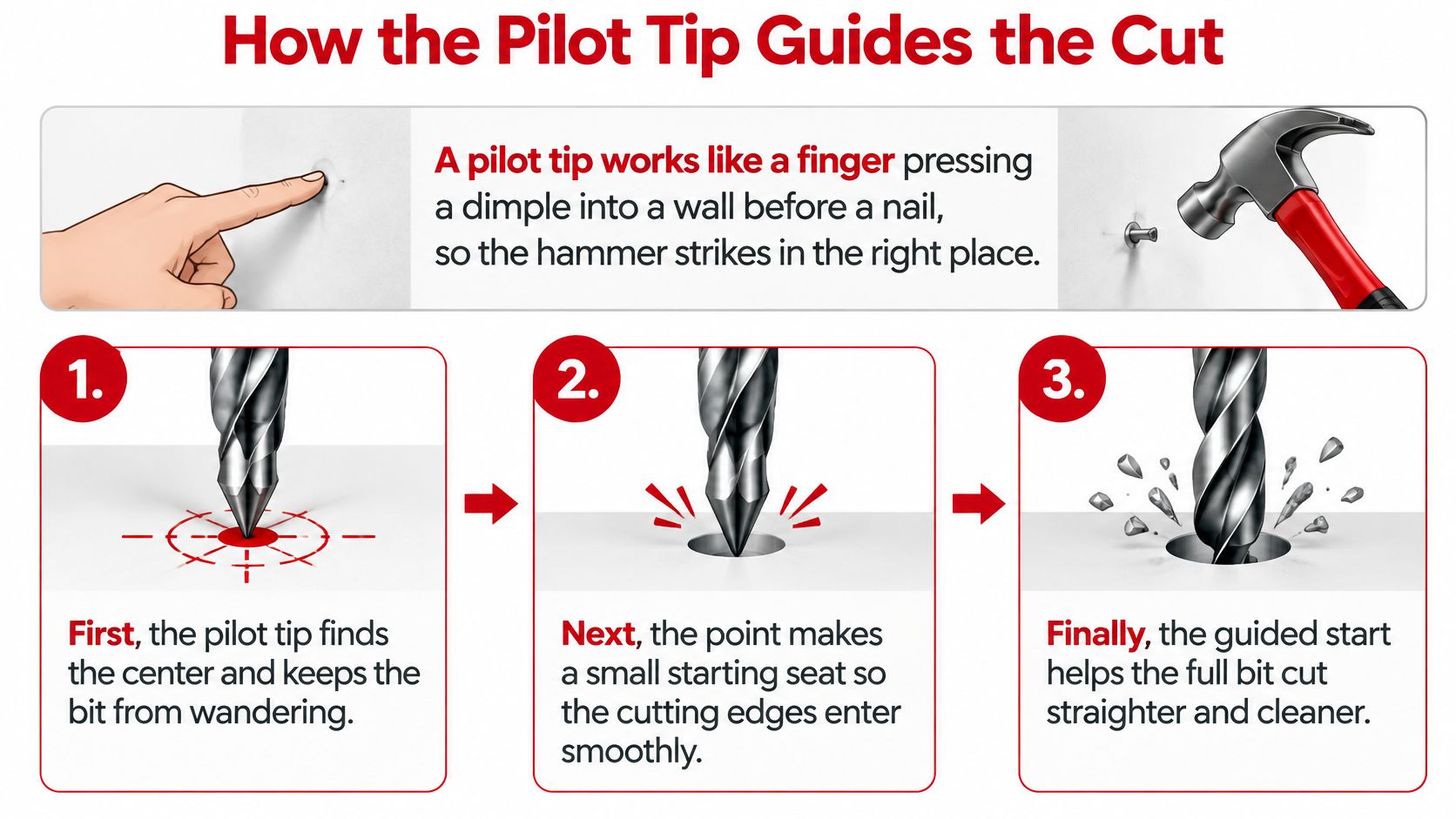
A 2023 study of drill-point geometry in AA1050 aluminum reported that a pilot-hole configuration decreases cutting force, and the same modeling tracked thrust force, torque, temperature, and plastic strain. The pilot portion sits ahead of the main cutting section, sometimes as a split point, so the small tip can bite before the full lips take a cut.
What you should see: the hole starts on the mark, and the bit holds that line as the full diameter deepens.
That hold stops at breakthrough. On thin sheet the tip pops free while the lips are still cutting the last skin of metal, so nothing is steering the exit. On layered stock, metal over wood or a stack of sheet, the tip can already be in the soft layer while the lips are still in the hard one. The center the tip just made no longer controls the hole. Wander, a torn rim, or a burr on the back face is the usual result. The pilot is an entry feature, not a strategy for the whole depth.
That centered start also matters when the hole is only there to accept a fastener. A set of #10 Fastgrip hi-lo metal-to-wood screws still needs the clearance hole in the metal on the layout, or the screw pulls the joint off the line no matter how well the threads bite the wood.
Point Angle, Pilot Size and Clearance That Matter
A mark sits on thin sheet, or on two skins with a softer layer between them. The pilot finds that mark and the hole looks won. It is not. Point angle, pilot length, and the clearance behind the lips still decide whether the full diameter cuts a round hole, and whether the far side tears after the little tip has already left the stock.
The pilot is an entry feature, not the whole drilling plan. Harder materials generally need larger point angles. Softer materials favor sharper angles so the bit grips instead of skating, chattering, or wearing a bell-mouthed hole. A sharp point finds the surface the way a knife finds grain. A blunt point spreads the load the way a wedge does, which is useful in hard metal and clumsy in soft fiber.
| Material | Typical point angle | Why this angle |
|---|---|---|
| Softwood and plastics | Near 90 degrees | Sharper tip grips and avoids pushing the material |
| Aluminum | Near 118 degrees | Balances chip flow and cutting force |
| Mild steel | Near 118 degrees | General-purpose reference angle for steel |
| Stainless and hard steel | About 135 degrees | Larger angle resists the high load of harder material |
| Composites such as CFRP | 130 to 140 degrees | In the Croatian CFRP point-geometry tests, the smaller angle in this range reduced surface roughness |
Treat those angles as shop reference values and check the maker's listing before you commit an expensive bit. A sharp 90-degree point in hardened steel loads the corners and burns them. A blunt 135-degree point in pine pushes fibers aside instead of slicing them.
Where the angle trade-off gets sharp
Composites don't follow the simple "harder means blunter" rule. A Croatian technical paper on point geometry found that changing the point from 140° to 130° substantially reduced CFRP surface roughness under the tested conditions, and that point angle was the largest contributor to delamination damage, at 47.66% of the measured effect. You can improve the look of the wall and still lift the plies, or protect the plies and leave a rougher bore. On thin or layered stock the pilot punches through before the main lips finish, so the angle that steadied the entry no longer controls the exit.
Pilot size and clearance decide how that tip enters. They do not finish the far side for you. A pilot that's too long and skinny can snap on the first hard spot. Clearance that's too small rubs, heats, and polishes the hole instead of cutting it. On aluminum, feed rate moves force and hole quality, including burrs and size, more than spindle speed does. Spinning faster won't fix a feed you are pushing too hard.
Self-centering can clean up the start. It can't rescue a point angle that fights the workpiece, or a feed that mashes the chisel into the cut.
Match the angle to the material first, then pick the tip style. For clean bores in timber, a wood drill bit with a spur often beats a metal pilot point, because the spur severs fibers the metal point only wedges apart. Once that metal point has found the mark and left a thin exit, its geometry has stopped helping.
Real Jobs Where the Pilot Tip Earns Its Place
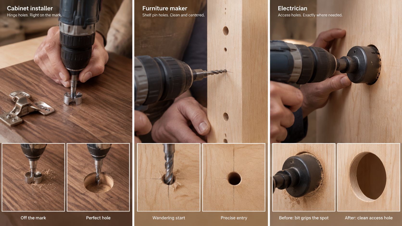
Three ordinary jobs show where the tip pays for itself, and where you still have to manage the rest of the cut.
Hinge plates in hardwood. A cabinet installer marks screw centers on a stile. Without a seated start, the bit drifts toward the softer grain and the hinge leaf sits crooked. With the pilot on the cross, each screw hole lands on the layout, and the plate closes without a second, oversized pass. The same logic applies outdoors: once the holes are true, you can compare corrosion-resistant deck screws for the lumber instead of fighting a row of holes that don't share a line.
Mild steel brackets. On a flat fab plate, a pilot-point bit starts on the scribed intersection and stays there. A plain twist bit on the same plate walks, so you stop, punch, and start again. The centered start is what keeps you from ovaling the hole while you try to drag it back on location. If the hole is already off, opening it only hides the miss. It doesn't put the center back.
Aluminum channel at the bench. The pilot holds the hole on the mark along a thin wall that wants to flex. Ease the feed as the tip nears the far side, or the exit burr grabs and the channel rings. For a run of holes in light sheet, the method in how you drill sheet metal is often the better next step than forcing a twist bit through every size.
These jobs favor the tip only when the bit's angle suits the material and the feed stays steady. Look up that angle for the stock you're holding, then set the drill before you commit the first hole in the finished part.
How to Drill One Hole With a Pilot-Point Bit
One clean hole teaches you more about a pilot-point bit than a row of rushed ones. A 3 mm pilot-point bit in a mild steel bracket is a fair practice piece: mark the center, use a general steel point near 118 degrees, and let the drill maker's speed chart beat any guess you carry in your head.
- Mark the exact center with a pencil cross, and confirm the point angle suits the material.
- Chuck the bit straight, spin it by hand to watch for wobble, and tighten the jaws fully. Runout here becomes an oversized hole later.
- Set a low spindle speed for hard metal and a medium speed for wood. Seat the pilot on the mark before you pull the trigger.
- Start slowly and let the pilot cut a small dimple before you add pressure. If it hasn't seated, stop. Reposition rather than pushing harder.
- Feed steadily. In metal and in deep holes, back out every few millimeters so chips can leave. Packed flutes are what overheats the corners.
- Ease the feed as the tip nears the far side. Once the pilot is through, its guiding work is done, and the last of the cut depends on your feed hand, not the geometry.
- Withdraw while the bit is still turning slowly, then check the diameter with a pin or gauge before you drill the matching holes.
The same seated-pilot logic scales up to larger openings. On thin metal, a separate pilot often leads a hole cutter so the teeth meet a located cut instead of slamming flat stock. The Carbide Hole Saw Drill Bit/Center Pilot Drill Bit takes that first hit on the surface before the hole saw teeth engage. It steadies the start and nothing more. Speed and feed still come from the chart for the hole saw body, the same way they do for a twist bit.
That division of labor is the whole idea. The pilot owns the entry. Chip clearing, steady feed, and a lightened hand own the middle and the exit. The drill and bit maker's figures take priority over any single "right" rpm, and if the tip blues, you're too fast, too dull, or both.
When the Pilot Tip Causes Breakout and Burrs
Every advantage the pilot geometry gives you lives on the entry side. The moment the tip shoves through the far side of thin or layered stock, the last fibers or the last skin of metal have nothing left to support them, and the shape of the point stops being the deciding factor.
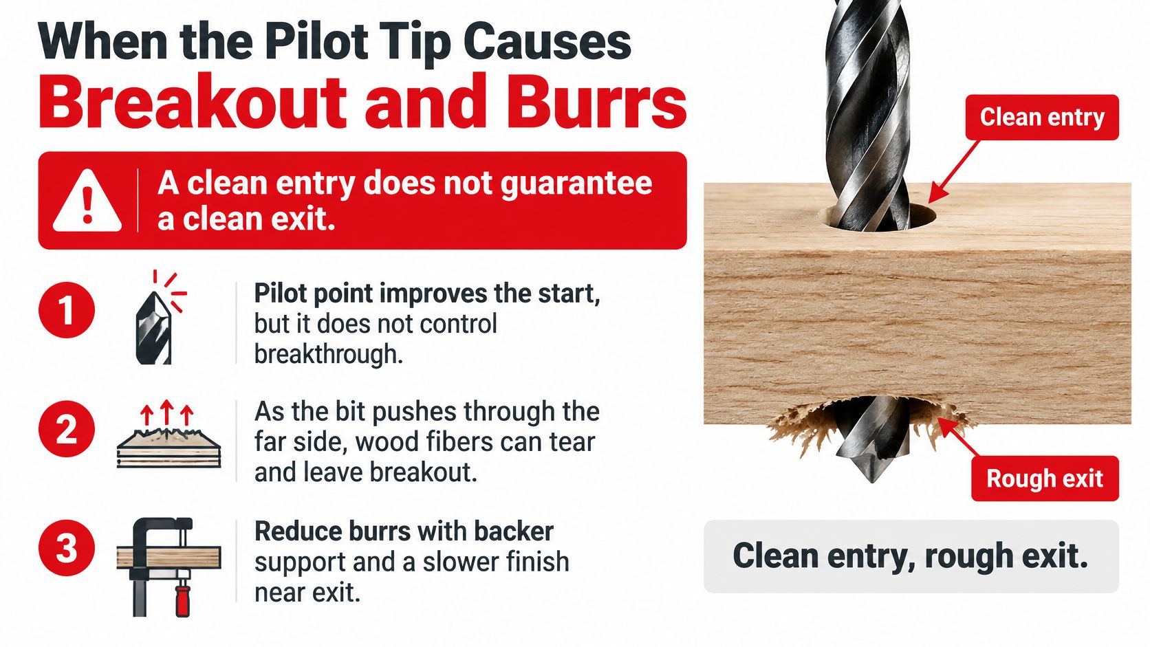
Hole quality at the exit comes from several settings acting together. A review of drilling variables in layered materials ties thrust force, hole diameter, surface roughness, and chip formation to feed rate, spindle speed, helix angle, clearance angle, chisel-edge geometry, and point angle. On CFRP and aluminum stacks, an optimized geometry described in that review used a 130° point angle, a 30° helix, and specified clearance and chisel-edge angles. A generic pilot-point bit isn't that geometry. On woven CFRP, a step tool whose first section pre-forms a pilot can cut thrust and lower delamination risk. Larger point angles can ease entry damage in some stacks and still worsen the exit.
Symptoms, causes, and the fix
| Symptom | Likely cause | Fix |
|---|---|---|
| Burr on the exit side | Feed too high at breakthrough | Reduce feed as the tip exits and deburr the edge |
| Splintering or tear-out on the far side | Thin or unsupported stock | Clamp a backing board or sacrificial layer behind the workpiece |
| Hole wanders at the start | Bit has no pilot, or pilot not seated | Use a pilot-point bit or mark and punch the center |
| Overheated tip or discoloration | Excess speed or dull cutting lips | Lower spindle speed, sharpen the bit and clear chips |
| Hole oversized or out of round | Pilot runout or worn bit | Check chuck and bit alignment, then replace the bit |
The repair sequence is short. Reduce feed at breakthrough. Back thin stock with scrap clamped tight, not just held by a hand. Clear chips before the flutes pack. Inspect both faces, not only the side you were watching. A burr that has already formed can be dressed off the exit face, but preventing it with backing and a lighter final feed costs less time than cleaning it up after.
In wood, a countersink often follows the pilot so the screw head sits flush without crushing the rim. The EZARC 12PCS Titanium Countersink Drill Bit Set with 5 Extra Pilot Bits and Case for Wood, Hardwood, Softwood is a 12-piece titanium-coated set for wood, hardwood and softwood, supplied with five extra pilot bits and a storage case. The pilot bit is doing the centering work, so when it dulls, fit one of the spares rather than leaning harder on a worn tip.
Misconceptions and Final Pre-Drill Checks
Four beliefs cause most of the bad holes.
A pilot-point bit seats itself on flat stock. Curved, shiny, or very hard faces still want a punch mark or a dead-slow start, since the tip needs a dimple or a gentle first bite to register. A larger point angle resists load in hard stock, yet on a layered stack it can still pry the plies apart at the exit. The pilot's steering ends where the body of the bit takes over, so breakthrough belongs to feed, backing, and the bit you chose. Chuck runout, a worn tip, or too much speed can erase the centering you paid for before the hole even starts.
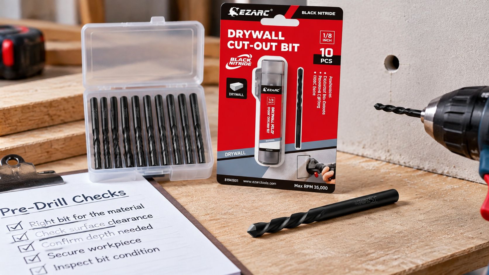
Five checks before drilling the finished part
Name the material and how hard it is. Mild steel, stainless, plywood, and a carbon-fiber skin are four different cuts.
Match the point angle to that material using the reference table, then confirm the listing on the bit.
Pick the tip for the start you need. A pilot-point or step design when the hole must land on a mark in metal or mixed stock. A brad-point when the hole is in wood and the rim has to stay crisp.
Back thin or layered stock and ease the feed as the tip breaks through. By then the pilot has already passed through and nothing is steering, so clamped scrap does that job.
Look at both sides and deburr before anything gets assembled. A burr you leave will cock a bracket or split a screw head.
For light sheet such as drywall, wood, and plastic, our 1/8 Inch Drywall Guidepoint Cutting Bits with Storage Case for Drywall Wood Plastic come in a storage case and start from $16.97. When the job is stepped holes in metal, stainless, aluminum, or plastic, the EZARC step drill bit set is listed from $23.97. Run either one through the checks above, then drill a test hole in scrap and read both faces before you touch the finished piece.
EZARC Tools carries drilling accessories for the start, the bore, and the countersink, including pilot-point bits, step drills, and countersink sets sized for wood and metal. Match the tip and the point angle to the stock you're cutting, then see the current listings at EZARC Tools and prove the setup on scrap before the first hole in the part.